×
Aircraft / Aviation Vehicles & Artillery Small Arms Warships & Submarines Military Ranks Military Pay Scale (2024) Special Forces

Curtiss VF-11


Carrierborne Interceptor Proposal


United States | 1947


"The Curtiss VF-11 was unsuccessfully proposed as a United States Navy carrierborne fighter-interceptor in the immediate post-World War 2 years."

Authored By: Staff Writer | Last Edited: 06/06/2022 | Content ©www.MilitaryFactory.com | The following text is exclusive to this site; No A.I. was used in the generation of this content.

In the path towards a viable post-World War 2 high-performance fleet defender, the United States Navy (USN) laid down the groundwork for what was to become Specification "OS-113" in 1948. As with land-based interceptors, this new, all-modern design would feature an exceptional rate-of-climb once in the air, made possible through turbojet technology and (possibly) rocket-boosted assistance. The requirement centered on a single-seat design and, it being a naval aircraft at heart, should showcase those qualities common to maritime-based combat operations including a deck-launching quality, arrestor hook landing feature, and folding wing mainplanes.

As a "fleet defender", this new fighter would have to respond in short order to the initial ping on ground-based radar. From there, the aircraft would have to launch, at-speed, and drive to altitude to meet the inbound threat. Since operational range was not so much an issue in this design, engineers would be allowed some flexibility in the end-product concerning fuel stores and fuel burn. At the end of the day, the aircraft needed to be fast (approximately 450 miles-per-hour straightline speeds), powerful (most likely through twin jet-engines), and hold an armament suite capable of dealing with the airborne threat (either large-caliber automatic cannons or fin-stabilized aerial rockets) - threats of the time being primarily Soviet in nature. Altitude needed to be reached in under four minutes and direction to the target area was to be had by AN/APG-22 series X-band gun radar system coupled with an Mk 1Fire Control System (FCS).

While the requirement was eventually met by, not one but two, fighters - the Douglas F4D "Skyray" and McDonnell F3H "Demon" - there were several other proposals drawn up prior to and during this period that included the usual Navy defense players such as Curtiss.

For the Curtiss concern, these emerged through drawings sponsored from 1946 onwards, following the close of World War 2 and prior to the official USN specification of 1948. For their part in the story, these attempts were laid out to "see into the future" regarding USN fighter needs resulting in the Curtiss "VF-11" which then evolved to become a series of fighter proposals all centered on a hoped-for Navy requirement as it geared up for work against the Soviet Union. This initiative begat the original VF-11 and the subsequent VF-11A and the VF-11B proposals all of which appeared in the latter part of 1946.

For the original VF-11, the planform that Curtiss engineers settled on was a "tailed delta" with clipped mainplane tips - resulting in an elegant arrow-like shape showcasing inherently clean lines, solid stability / control, and increased internal volume for components such as avionics, armament, and fuel. The delta-wing planform also negated the use of horizontal tailplanes in the design, creating a three-winged shape with fewer obstructions (and therefore less drag) instead. Beyond the expansive surface area were large-area surface controls for maximum agility at each of the plane trailing edges. The rudder fin was of particular note as it was another large-area plane, reaching high above the cockpit line, and had a curved edge.

In the arrangement, the single crewman could take up his position at the nose under a three-piece canopy with armament featured along the left side of the nose (in this case a single rocket-launching tube-like system). To aspirate the engine pairing, intakes were seated along the sides of the fuselage (since the rocket motor was not an air-breathing engine, it did not require an intake). The single vertical fin was affixed over the empennage and sat over the exhaust ports at the rear. For ground-running, a standard tricycle undercarriage would be used showcasing a nose wheel on an extended leg and shorter main legs under center mass.

To cover the extreme performance requirements, the company would rely on 2 x Westinghouse 24C-4B afterburning turbojet engines of 3,000 lb (dry) to 4,200 lb thrust (with reheat) coupled with an additional 1,000lb of thrust to come from a dedicated, single-use, short-burn rocket booster / motor for instant acceleration. Combined, the arrangement would give this fleet defender considerable performance as it cut its way through the skies to reach threats as high up as 40,000-to-45,000 feet out to a range of 100 miles from the carrier. The engines were to be seated in the middle-aft section of the fuselage in a conventional side-by-side arrangement.

Armament of this design was a departure from the usual assortment of heavy machine guns or automatic cannons favored by American warplanes of the war period. Instead, a wholly-rocket suite was envisioned for the interceptor - giving appropriate firepower against any aerial threat of the day. Up to six 5" (127mm) High-Explosive (HE) aerial rockets were to be carried and these launched through an opening cut out at the lower left side of the fuselage (port side).

At any rate, the VF-11 was not furthered beyond its paper stage and the VF-11A and VF-11B followed with the same result. The A-model offering simplified the approach by using a single British Rolls-Royce turbojet engine with reworked intakes and was given a clipped tail rudder. The B-model was completely rearranged to feature a more conventional mainplane arrangement though with outward-canted "V-style" tailplanes.

Content ©MilitaryFactory.com; No Reproduction Permitted.
Power & Performance
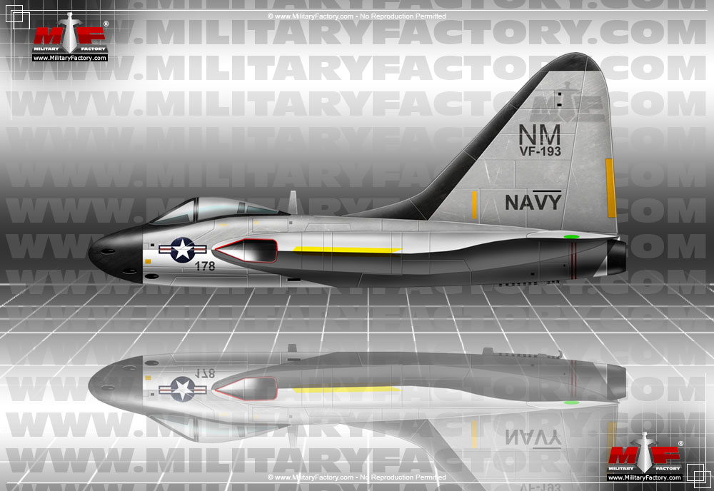
Those special qualities that separate one aircraft design from another. Performance specifications presented assume optimal operating conditions for the Curtiss VF-11 Carrierborne Interceptor Proposal.
2 x Westinghouse 24C-4B afterburning turbojet engines developing 3,000lb dry thrust and 4,200lb thrust with reheat; 1 x Rocket booster motor generating additional short-term thrust of 1,000lb rating.
Propulsion
659 mph
1,060 kph | 572 kts
Max Speed
50,033 ft
15,250 m | 9 miles
Service Ceiling
20,000 ft/min
6,096 m/min
Rate-of-Climb
Structure
The nose-to-tail, wingtip-to-wingtip physical qualities of the Curtiss VF-11 Carrierborne Interceptor Proposal.
1
(MANNED)
Crew
29.9 ft
9.10 m
O/A Length
31.5 ft
(9.60 m)
O/A Width
10,141 lb
(4,600 kg)
Empty Weight
11,872 lb
(5,385 kg)
MTOW
Armament
Available supported armament and special-mission equipment featured in the design of the Curtiss VF-11 Carrierborne Interceptor Proposal .
PROPOSED:
6 x 5" (127mm) High-Explosive (HE) spin-stabilized aerial rockets launched from lower fuselage port side.
Variants
Notable series variants as part of the Curtiss VF-11 family line.
VF-11 - Base Fighter Proposal of 1946.
VF-11A - Revised proposal with squared-off vertical tail fin and single Rolls-Royce turbojet engine.
VF-11B - Revised proposal showcasing more traditional fighter design mainplane wing arrangement; outward-canted V-style tail unit.
Operators
Global customers who have evaluated and/or operated the Curtiss VF-11. Nations are displayed by flag, each linked to their respective national aircraft listing.

Total Production: 0 Units

Contractor(s): Curtiss - USA
National flag of the United States

[ United States (cancelled) ]
1 / 1
Image of the Curtiss VF-11
Image copyright www.MilitaryFactory.com; No Reproduction Permitted.

Similar
Developments of similar form-and-function, or related, to the Curtiss VF-11 Carrierborne Interceptor Proposal.
Going Further...
The Curtiss VF-11 Carrierborne Interceptor Proposal appears in the following collections:
HOME
AVIATION INDEX
AIRCRAFT BY COUNTRY
AIRCRAFT MANUFACTURERS
COMPARE AIRCRAFT
AIRCRAFT BY CONFLICT
AIRCRAFT BY TYPE
AIRCRAFT BY DECADE
COLD WAR AIRCRAFT
X-PLANE AIRCRAFT
Disclaimer | Privacy Policy | Cookies

2024 Military Pay Scale Military Ranks of the World U.S. Department of Defense Dictionary Conversion Calculators Military Alphabet Code Military Map Symbols Breakdown U.S. 5-Star Generals List WWII Weapons by Country World War Next

The "Military Factory" name and MilitaryFactory.com logo are registered ® U.S. trademarks protected by all applicable domestic and international intellectual property laws. All written content, illustrations, and photography are unique to this website (unless where indicated) and not for reuse/reproduction in any form. Material presented throughout this website is for historical and entertainment value only and should not to be construed as usable for hardware restoration, maintenance, or general operation. We do not sell any of the items showcased on this site. Please direct all other inquiries to militaryfactory AT gmail.com. No A.I. was used in the generation of this content.

Part of a network of sites that includes GlobalFirepower, a data-driven property used in ranking the top military powers of the world, WDMMA.org (World Directory of Modern Military Aircraft), WDMMW.org (World Directory of Modern Military Warships), SR71blackbird.org, detailing the history of the world's most iconic spyplane, and MilitaryRibbons.info, cataloguing military medals and ribbons. Special Interest: RailRoad Junction, the locomotive encyclopedia.


©2024 www.MilitaryFactory.com • All Rights Reserved • Content ©2003-2024 (21yrs)