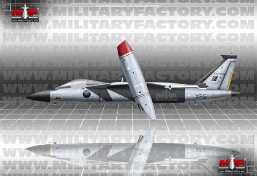
During the 1970s and 1980s, British studies into Vertical Take-Off and Landing (VTOL) fighter aircraft reached a fever pitch. While a mountain of designs were eventually drawn up, many would never see the light of day or exist solely as proposals rejected by higher-ups. The British Aerospace (BAe) concern certainly contributed to the effort by way of their Warton and Kingston sites during a period where no seemingly terrible idea was "off the table".
The P.103 project fighter emerged from the Warton location and this offering was one of the more unique designs to come out of the company during this time. The primary feature of the aircraft was its engines housed in underslung, outboard nacelles that could tilt to offer the needed VTOL performance and also coming in-line to provide the required forward propulsion. Design work on this single-seat, twin-engine solution was begun in 1978 with the hope that flight-testing could be had before the middle of the 1980s.
The tilting action of the engines, mounted to the mainplanes, necessitated a non-traditional arrangement in which foreplanes at the front of the fuselage sides took the place of conventional tailplanes normally positioned at the rear near the engine exhaust port. The mainplanes themselves were conventionally rear-swept with the engine nacelles positioned at their midway point. The members were shoulder-mounted along the sides of the semi-rounded fuselage and sported dihedral inboard and anhedral outboard of the engine housings. Control surfaces would have to be spread about the angled leading and trailing edges where possible due to the engines braking up the wing design.
The engine housings were essentially rounded-rectangles with circular intakes for aspiration and exhaust ports. The tail unit featured a single vertical plane and sat stop the tapering end of the fuselage which terminated at a shallow rounded cone. The single-seat, pressurized cockpit (no doubt sporting an ejection seat) was positioned ahead of the wing surfaces and aft of a traditional nosecone (to house radar in the finalized design). A wheeled / retractable tricycle undercarriage would be used for ground-running - the nose leg disappearing under the cockpit floor and the main legs pulling into the cramped fuselage section.
The Turbo-Union RB.199 turbofan (developed by the joint venture involving Rolls-Royce of Britain, MBB of West Germany, and Aeritalia of Italy) was at the center of the propulsion scheme. The units were short enough to be featured in the tilting engine arrangement and, more importantly, offered the inherent power required of the VTOL action. The mechanical system was to be able to move the engine through a range of up to 90-degrees - not only allowing for runway-free operation, but also shortening take-off runs if the fighter was operated in the usual, conventional take-off manner.
Beyond wind tunnel testing to prove aerodynamics sound, a full-sized mockup was completed at the Warton facility during 1980. However, the design did not proceed beyond this stage as its inherent complexity naturally doomed the venture before it went airborne. The mechanism needed to manage the tilting function was just one issue - the other being the loss of one engine in the design (due to failure and whatnot) destined to doom the entire aircraft and pilot in one fell swoop.
One short-lived version of this same aircraft study reworked the mainplanes to be forward-swept / forward-cranked. Interestingly, the foreplanes were retained as rearward-swept appendages.
Note: The above text is EXCLUSIVE to the site www.MilitaryFactory.com. It is the product of many hours of research and work made possible with the help of contributors, veterans, insiders, and topic specialists. If you happen upon this text anywhere else on the internet or in print, please let us know at MilitaryFactory AT gmail DOT com so that we may take appropriate action against the offender / offending site and continue to protect this original work.
(OPERATORS list includes past, present, and future operators when applicable)
✓Air-to-Air Combat, Fighter
General ability to actively engage other aircraft of similar form and function, typically through guns, missiles, and/or aerial rockets.
✓Ground Attack (Bombing, Strafing)
Ability to conduct aerial bombing of ground targets by way of (but not limited to) guns, bombs, missiles, rockets, and the like.
✓Close-Air Support (CAS)
Developed to operate in close proximity to active ground elements by way of a broad array of air-to-ground ordnance and munitions options.
✓X-Plane (Developmental, Prototype, Technology Demonstrator)
Aircraft developed for the role of prototyping, technology demonstration, or research / data collection.
VERTICAL TAKE-OFF / LANDING (VTOL)
Series has a tactical capability to take-off and / or land vertically, a quality commonly associated with helicopters.
RADAR-CAPABLE
Houses, or can house (through specialized variants), radar equipment for searching, tracking, and engagement of enemy elements.
MULTI-ENGINE
Incorporates two or more engines, enhancing survivability and / or performance.
CANARDS
Small foreplanes ahead of the mainplanes reduce wing-loading and / or enhance maneuverability during high angle-of-attack or stall actions.
HIGH-SPEED PERFORMANCE
Can accelerate to higher speeds than average aircraft of its time.
PILOT / CREW EJECTION SYSTEM
Assisted process of allowing its pilot and / or crew to eject in the event of an airborne emergency.
CREWSPACE PRESSURIZATION
Supports pressurization required at higher operating altitudes for crew survival.
ENCLOSED CREWSPACE(S)
Features partially- or wholly-enclosed crew workspaces.
RETRACTABLE UNDERCARRIAGE
Features retracting / retractable undercarriage to preserve aerodynamic efficiency.
Length
50.0 ft (15.25 m)
Width/Span
42.0 ft (12.80 m)
(Showcased structural values pertain to the base BAe P.103 production variant)
monoplane / shoulder-mounted / swept-back, w canards OR swept-forward, w canards
Monoplane
Design utilizes a single primary wing mainplane; this represent the most popular mainplane arrangement.
Shoulder-Mounted
Mainplanes are mounted at the upper section of the fuselage, generally at the imaginary line intersecting the pilot's shoulders.
Swept-Back
The planform features wing sweep back along the leading edges of the mainplane, promoting higher operating speeds.
Swept-Back, with Canards
The planform features wing sweep back along the leading edges of the mainplane, promoting higher operating speeds, with added controlling provided through smaller foreplanes ('canards') seated ahead of the mainplanes.
Swept-Forward (Forward Cranked)
The mainplanes showcase a forward sweep of the leading and trailing edges.
Swept-Forward, with Canards
The mainplanes showcase a forward sweep of the leading and trailing edges while the arrangement also relies on added controlling through smaller foreplanes ('canards') seated ahead of the mainplanes.
(Structural descriptors pertain to the base BAe P.103 production variant)
Installed:
2 x Turbo-Union (Rolls-Royce, MBB, Aeritalia) RB.199-62R afterburning turbofan engines developing 20,750lb of thrust dry and up to 37,850lb of thrust with reheat; engines fitted to wing mainplane member tiling mechanism for VTOL operations.
(Showcased performance specifications pertain to the base BAe P.103 production variant. Performance specifications showcased above are subject to environmental factors as well as aircraft configuration. Estimates are made when Real Data not available. Compare this aircraft entry against any other in our database or View aircraft by powerplant type)
ASSUMED:
2 x 20mm internal automatic cannons in lower forward fuselage.
2 x Air-to-Air Missiles (AAMs) at wingtips (one per wing member).
Other hardpoints to carry additional AAMs and most likely plumbed for jettisonable fuel tanks to extend inherent operational ranges.
Supported Types
(Not all ordnance types may be represented in the showcase above)
Hardpoint Mountings: 2
Mounting Points
15
-
-
-
-
-
-
-
-
-
-
-
-
-
14
HARDPOINT(S) KEY:
X
15
13
11
9
7
5
3
1
2
4
6
8
10
12
14
COLOR KEY:
Fuselage Centerline
Fuselage Port/Wingroot
Fuselage Starboard/Wingroot
Wing/Underwing
Wingtip Mount(s)
Internal Bay(s)
Not Used
Note: Diagram above does not take into account inline hardpoints (mounting positions seated one-behind-the-other).
P.103 - Project Designation; full-scale mockup completed before project's end.
Ribbon graphics not necessarily indicative of actual historical campaign ribbons. Ribbons are clickable to their respective aerial campaigns / operations / aviation periods.
Images Gallery
1 / 1
Image copyright www.MilitaryFactory.com; No Reproduction Permitted.
The "Military Factory" name and MilitaryFactory.com logo are registered ® U.S. trademarks protected by all applicable domestic and international intellectual property laws. All written content, illustrations, and photography are unique to this website (unless where indicated) and not for reuse/reproduction in any form. Material presented throughout this website is for historical and entertainment value only and should not to be construed as usable for hardware restoration, maintenance, or general operation. We do not sell any of the items showcased on this site. Please direct all other inquiries to militaryfactory AT gmail.com. No A.I. was used in the generation of this content; site is 100% curated by humans.